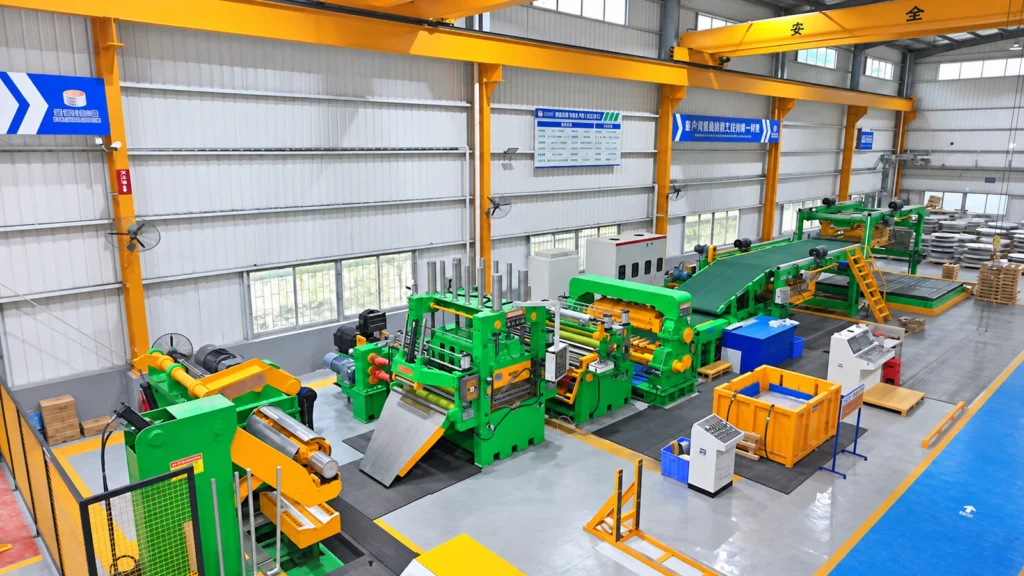
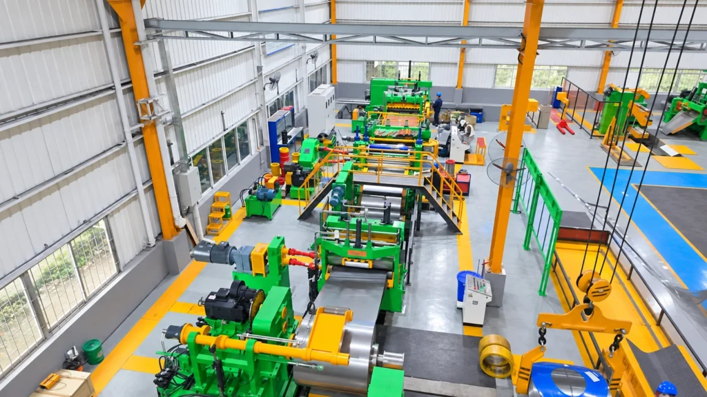
For surface-critical aluminum sheet, the cut-to-length shear is not selected on cutting speed alone. The key question is whether the strip can continue moving through the leveler while each sheet is cut. That is why many aluminum cut-to-length projects favor a flying shear or tracking shear arrangement: the shear synchronizes with the moving strip instead of requiring the strip to pause for every normal cut.
The reason is practical. When a stop-shear cycle makes the strip decelerate or stop while it is inside a loaded leveler, the aluminum may remain in static contact with the work rolls. Dwell under roll contact, changes in strip tension, roll contamination, or a transient slip at restart can all increase the risk of visible roller marks or local flatness variation. On bare, bright, coated, brushed, or film-protected aluminum, a surface imperfection that may be tolerated on another material can become a customer-facing quality issue.
This does not mean that every aluminum cut-to-length line must use a flying or tracking shear. A well-designed stop-shear line can suit slower, less surface-sensitive work. But when the material surface and finished-sheet appearance are critical, continuous travel through the leveling section is often the safer process principle.
The short answer: protect continuous leveling
A precision leveler removes coil set and improves sheet flatness by passing strip through a controlled series of work rolls. The process is most stable when strip movement, entry tension, exit tension, and roll contact are managed as one continuous condition. In a conventional start-stop cutting cycle, that condition changes repeatedly: strip speed falls, strip may stop, then the line accelerates again.
For aluminum, the concern is not simply that the machine has “stopped.” It is the combination of surface sensitivity and contact conditions while stopped. If the strip remains held against loaded rolls for longer than intended, any slight roll contamination, variation in roll condition, local pressure difference, or tension imbalance has more opportunity to transfer a visible mark. Restarting can add another disturbance if the strip does not regain stable tension and tracking immediately.
Roller marks are therefore a risk to be controlled, not an automatic result of every stop. The risk becomes more important when the product has a demanding cosmetic finish, a thin or easily marked surface, frequent short-length cuts, or a production rhythm that would create many start-stop cycles per coil.
How flying and tracking shears change the process
A flying shear cuts while the strip is moving. The cutting mechanism accelerates and synchronizes with line speed for the cutting portion of its travel, then returns and prepares for the next sheet. A tracking shear follows the same production objective: its cutting motion is coordinated with the moving material so that the main strip flow is not interrupted by each normal cut.
Terminology and mechanics vary by supplier. “Flying shear,” “tracking shear,” and some rotary-shear arrangements can describe different cutting mechanisms. The common engineering objective is more important than the name: measure the moving strip accurately, synchronize the cut with strip travel, and keep the upstream leveling process stable.
With the strip kept in motion, the leveler can operate without the repeated dwell-and-restart pattern of a conventional stop-shear cycle. This supports a smoother material path through the leveling section, reduces the number of acceleration transients acting on the strip, and helps preserve a consistent surface-processing condition. It also improves production continuity when short sheet lengths would otherwise require frequent stops.

Why aluminum makes the choice more important
Aluminum is used in products where appearance can be part of the specification: appliance panels, architectural sheet, transport components, packaging stock, coated material, and many fabricated parts. The exact sensitivity depends on alloy, temper, thickness, finish, protective film, downstream forming, and the customer’s acceptance standard. Those conditions should be confirmed before selecting the line.
In a surface-critical application, the customer is not only buying a shear. They are buying the stability of the entire path from uncoiling to stacking. The leveler, bridle or pinch sections, loop control, length measurement, shear synchronization, conveyor, and stacker must work together without creating local pressure points, scuffing, or sudden tension changes.
A fly or tracking shear is especially worth evaluating when a project combines several of the following conditions:
- Bare, bright, coated, brushed, laminated, or otherwise appearance-sensitive aluminum sheet;
- Thin material or a finished sheet that must remain flat and visually clean;
- Short sheet lengths that create a high number of cuts per coil;
- High production output where repeated acceleration and deceleration would dominate the cycle;
- Strict downstream requirements for stamping, forming, painting, or exposed panels.
These conditions do not specify a machine by themselves. They identify the questions that the project team must solve. The right shear arrangement must be matched with the actual coil data and the required finished sheet.
A flying shear is not a substitute for good leveler practice
Continuous cutting reduces one important source of risk, but it cannot compensate for poor roll condition or poor handling. A surface-protection plan for aluminum should also review roll cleanliness, roll finish, roll runout, leveling pressure, strip tension, guiding accuracy, and the condition of every contact surface that touches the strip.
For example, a continuous line can still mark aluminum if a roll carries debris, if a damaged roll creates a repeating contact pattern, if strip tracking is unstable, or if the tension profile is unsuitable for the material. Likewise, a stop-shear line may produce acceptable material when the product is less surface-sensitive and the line has been engineered and validated for that duty.
The practical conclusion is simple: a flying or tracking shear protects process continuity, while the leveler and handling sections must still protect the surface. Both are necessary.
Can a stop shear still be used for aluminum?
Yes—subject to the project requirement. A stop shear can be appropriate where production speed is moderate, sheet lengths are longer, cosmetic surface requirements are less demanding, or the line arrangement isolates the leveling section from the cutting cycle. A dedicated accumulator or looper may, in some configurations, help decouple downstream cutting from upstream strip travel. Whether that approach protects the leveler from interruption depends on the actual layout, controls, available material storage, and operating sequence; it must be verified for the specific line.
It is therefore better to say that surface-critical aluminum usually favors a continuous shear solution, rather than saying stop shear is universally impossible. The supplier should demonstrate how the strip will move through the leveler during normal production, changeovers, and non-routine events—not only during an ideal cutting cycle.
What to verify before choosing the shear
A useful technical review should begin with the complete production target rather than a catalogue model. Provide the supplier with the following information:
- Aluminum alloy, temper, thickness range, width range, coil weight, and incoming surface condition;
- Whether the surface is bare, coated, brushed, laminated, or otherwise appearance-critical;
- Finished sheet lengths, length mix, allowable cut tolerance, diagonal requirement, and cut frequency;
- Required flatness and any customer-defined acceptance criteria for marks, scratches, or visual defects;
- Desired production rhythm and whether the leveler must remain in continuous motion during normal cuts;
- Required conveyor, stacking, protective-film, and material-handling arrangements;
- Representative coils for trial processing before final acceptance.
Ask the supplier to explain the synchronization logic between the line encoder, leveler, pinch or bridle rolls, and shear. For a flying or tracking solution, also request the travel profile, safe operating range, control architecture, and how the line behaves at changes of speed or sheet length. This converts a general “no roller marks” requirement into an engineering discussion that can be tested.

Related XIONGJIN references
For a visual reference to continuous cut-to-length production, see XIONGJIN’s high-speed 1650 flying-shear cut-to-length project. Where the material and surface requirement allow a different approach, the process can also be reviewed against XIONGJIN’s 1650 stop-shear cut-to-length line and 1650 rotary-shear cut-to-length-line. These pages are references for equipment type; final suitability must be confirmed against the actual coil and finished-sheet specification.
Conclusion
For surface-critical aluminum, the user’s concern is sound: keeping the strip moving through the leveler can reduce a key roller-mark risk. A flying or tracking shear does this by completing the normal cut in synchronization with strip travel instead of stopping the strip for every sheet. The correct line, however, is not selected by shear type alone. It must combine continuous motion with clean and suitable leveler rolls, stable tension, accurate synchronization, protected handling, and validation on representative aluminum coils.